
Within BS7671 the wiring regulations, Regulation 421.1.201 states that “within domestic (household) premises, consumer units and similar switchgear assemblies must comply with BS EN 61439-3…………”
In this article we will look at into some of the compliance requirements of BS EN 61439-3 and the responsibilities manufactures have to fulfil before certification is granted. Contactum are proud to be able to share excerpts taken directly from our Defender 2 test reports
Certification to BSEN 61439-3 requires a variety of tests to be performed (listed below). Certification will only be granted on successful completion of each test. These tests are onerous and designed to prove the unit is able to perform way past its normal expected operational design characteristics.
- RESISTANCE TO CORROSION
- VERIFICATION OF RESISTANCE OF INSULATING MATERIALS TO ABNORMAL HEAT AND
- FIRE DUE TO INTERNAL ELECTRIC EFFECTS
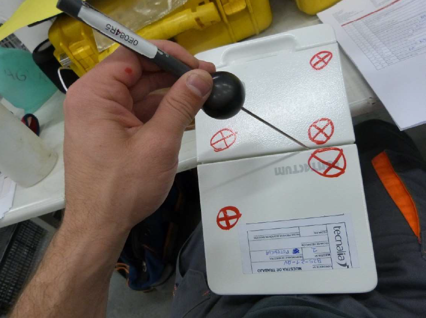
- VERIFICATION OF PROTECTION AGAINST MECHANICAL IMPACT (IK CODE)
- MARKING
- DEGREE OF PROTECTION (IP CODE)
- CLEARANCE AND CREEPAGE DISTANCES
- EFFECTIVE EARTH CONTINUITY BETWEEN THE EXPOSED CONDUCTIVE PARTS OF THE
- ASSEMBLY AND THE PROTECTIVE CIRCUIT
- SHORT-CIRCUIT WITHSTAND STRENGTH OF THE PROTECTIVE CIRCUIT. CONDITIONAL
- SHORT-CIRCUIT TEST
- INCORPORATION OF SWITCHING DEVICES AND COMPONENTS
- INTERNAL ELECTRICAL CIRCUITS AND CONNECTIONS
- TERMINAL FOR EXTERNAL CONDUCTORS
- POWER FREQUENCY WITHSTAND VOLTAGE TEST
- IMPULSE WITHSTAND VOLTAGE TEST
- TEMPERATURE-RISE TESTS
- SHORT-TIME WITHSTAND CURRENT TEST
- SHORT-CIRCUIT WITHSTAND STRENGTH TEST. 16 kA TEST WITH FUSE (ANNEX ZB)
- DIELECTRIC VERIFICATION
- ELECTROMAGNETIC COMPATIBILITY
- MECHANICAL OPERATION
Some of the tests are more critical than others, but all are mandatory for the unit to be certificated. Below, we have shared directly from our reports of some of the more arduous tests carried out.
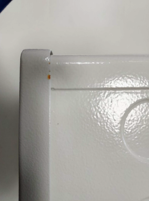
RESISTANCE TO CORROSION
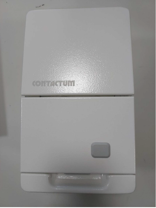
The test was performed according to BS EN 61439-3, Clause 10.2.2.2.
The test is performed on a representative enclosure with a degree of severity A.
The test consists of applying 6 cycles of 24 h each to damp heat cycling test according to IEC 60068-2-30:2005 (test Db) at 40 ºC and relative humidity of 95%. After that, 2 cycles of 24 h each to salt mist according to IEC 60068-2-11 at a temperature of 35 ºC were applied.
After the test, the enclosure is washed in running tap water for 5 min, in distilled or demineralized water then shaken or subjected to an air blast to remove water droplets.
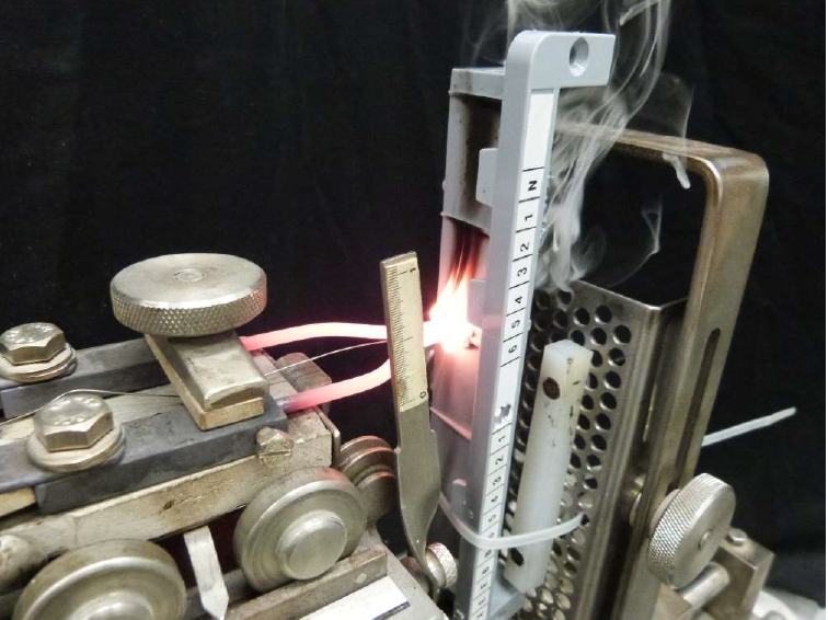
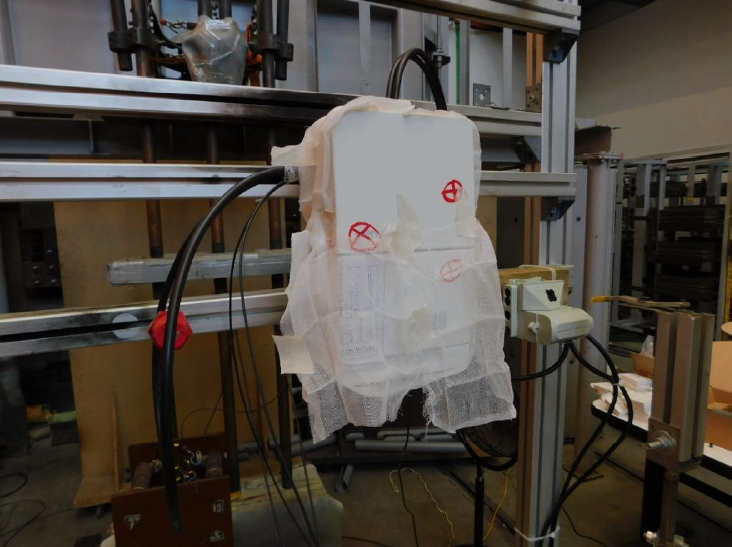
VERIFICATION OF RESISTANCE OF INSULATING MATERIALS TO ABNORMAL HEAT AND FIRE DUE TO INTERNAL ELECTRIC EFFECTS
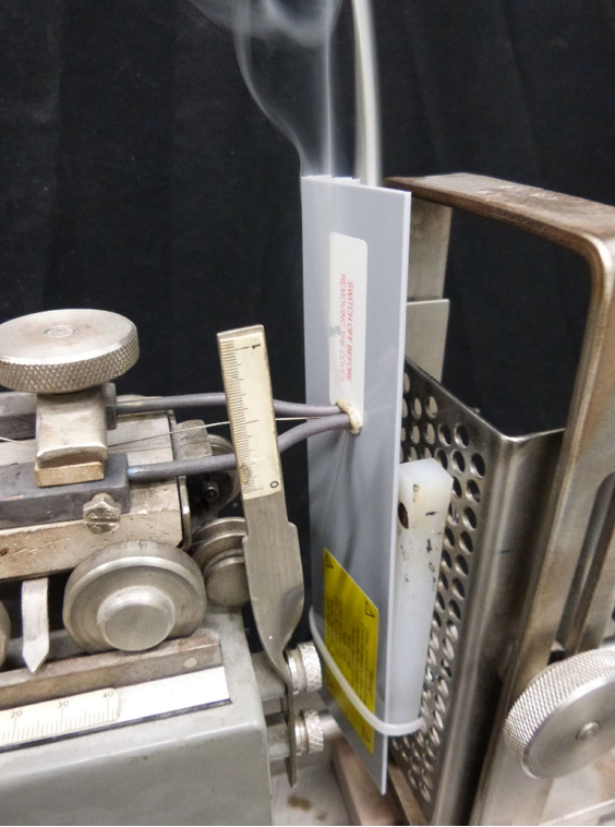
The test was performed according to BS EN 61439-3, Clause 10.2.3.2. Test performed on panel 1.
The test specimen is conditioned for at least 24 hours at a temperature between 15ºC and 35ºC and a
relative humidity between 45% and 75%. Once removed from the conditioning atmosphere, the test
specimen is tested within 30 minutes.
The wrapping tissue and the wooden board to be placed underneath the test specimen are specified in 5.3 of IEC 60695-2-10. They are conditioned for a minimum of 24 hours at a temperature between 15ºC and 35ºC and a relative humidity between 45% and 75%.
The test specimen is considered to have withstood this test if there is no ignition, or if all the following
situations apply.
a) the longest sustained and continuous flames or glowing of the test specimen after removal of the glow- wire extinguish within 30 s;
b) the specimen is not totally consumed; and
c) there is no ignition of the wrapping tissue.
6.2. Test parameters
The temperatures are as follows:
960 ± 15 ºC for insulating materials supporting live elements (terminal connectors)
650 ± 10 ºC for insulating materials not supporting live elements (cable support and isolating board).
DEGREE OF PROTECTION (IP CODE)
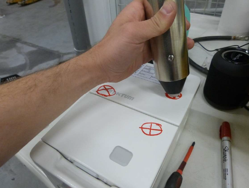
The test was performed according to BS EN 61439-3, Clause 10.3. Test performed on panel 1.
The verification of the degree of protection of the enclosure was conducted in accordance with IEC
60529:1989+AMD1:1999+AMD2:2013 standard.
The protection against access to dangerous areas and access of foreign particles, as well as ingress of
water was verified.
The assigned IP code: IP2XC
IP4X (only for the top)
Protection against access to dangerous areas
IP4X in the top, according to the first characteristic 4, the access probe of 1 mm diameter and 100 mm length applied with a force of 1 N ± 10% shall not access to dangerous mechanical or live parts.
TEMPERATURE-RISE TESTS
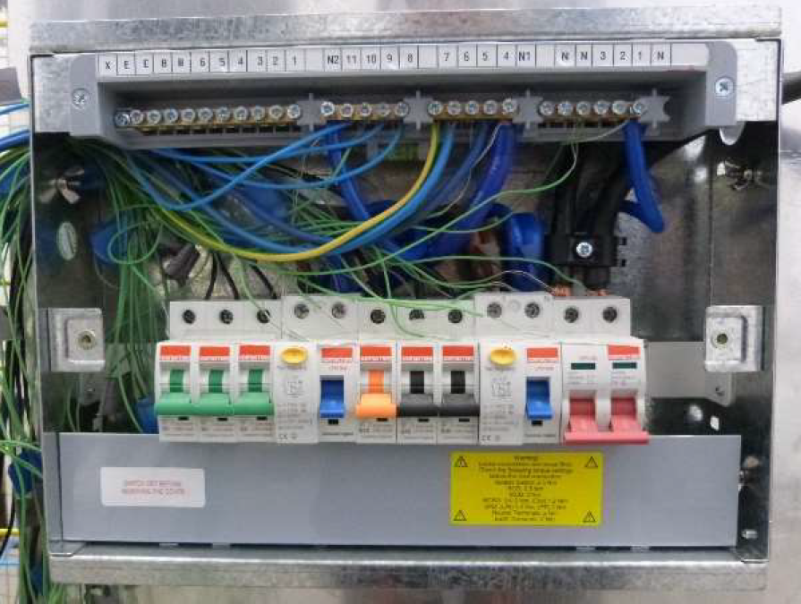
This test was performed according to BS EN 61439-3, Clause 10.10.2.3.5.
The loads distribution in the different tested panels, and the cables cross section, was as follows:
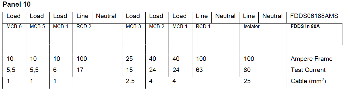
The temperature of the different parts was measured by thermocouples type K.
When this test is performed, a load is connected to the outgoing breakers as per the table. The temperature is monitored for heat rise.
The result: We have the full rating of board without derating the outgoing circuits.
SHORT-TIME WITHSTAND CURRENT TEST
This test was performed according to BS EN 61439-3, Clause 10.11.
The full current was applied to the main horizontal busbar.
The enclosure is connected to earth by a fuse element (copper wire of 0.8 mm diameter and 50 mm long) for the detection of fault currents.
Supply: A 35 mm2 copper cable connected to each side of the main busbar, total cable length
2.35 m
Test parameters - Main circuit
Itest (RMS): 10 kA
Itest (peak): 17 kA
Cos φ: 0.5
Time: 0.1 s
SHORT-CIRCUIT WITHSTAND STRENGTH TEST. 16 kA TEST WITH FUSE (ANNEX ZB)

This test was performed according to BS EN 61439-3, Clause 10.11.5.
The test object is place in a support with cotton of about 34 g/m2 placed in all the openings susceptible of emitting gases.
The test sequence is as follows:
O-t-CO
O: Breaking operation
CO: Making operation followed by a breaking operation
t: Interval between two successive short-circuit operations
After the test the insulating resistance must be measured with the following limits:
- 0.1 MΩ between the incoming terminals of the protective device, in open position, and the output
terminal.
- 0.25 MΩ between the protective device and the earth
The correct working of the residual current device is verified supplying with a voltage of 0.85 times the
nominal voltage.
The test is performed to units of maximum and minimum rating for any different outgoing unit tested.
Annex ZB of BS EN 61439-3 is a verification of the Consumer unit to withstand a 16kA fault. This is specific requirement for consumer units used within UK installations.
When choosing Defender 2, you are guaranteed a quality safe & beautifully designed consumer unit which meets the stringent requirements of BS EN 61439-3
Type test Certificates for all Defender 2 consumer units are available upon request